When football club KV Ostend (Belgium) in June 1981 was founded after the fusion of former clubs VG Ostend and AS Ostend, it inherited the facilities dating back from the early 60's. Due to the old facilities, the club was not allowed to play after its qualification for the European competitions in 2014. Important renovations had to be done to acquire a European license. To fulfill the modern requirements and regulations in terms of safety and accessibility, new stadium grandstands with precast concrete were built.
126
thema
Grandstands in
precast concrete
1
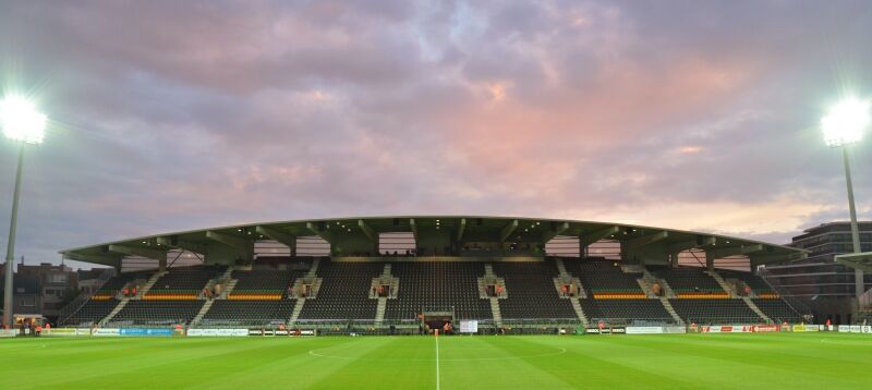
New football stadium with precast concrete structure
for Belgium football club KV Ostend
A need to comply
For the construction works of the new stadium of KV Ostend
an investment of 18 million ? was needed. The new stadium
structure was initially foreseen in steel. The general contractor
however, proposed an alternative in precast concrete; this
would result in short term cost reduction (no fire protection
needed) and long term cost reduction (less maintenance).
Eventually it was decided to build in precast concrete.
The work started in February 2016 with the demolition of the
main grandstand and two smaller grandstands. The rebuilding
When football club KV Ostend (Belgium) in June 1981 was founded
after the fusion of former clubs VG Ostend and AS Ostend, it inherited
the facilities dating back from the early 60's. Due to the old facilities,
the club was not allowed to play after its qualification for the European
competitions in 2014. Important renovations had to be done to acquire
a European license. To fulfill the modern requirements and regulations
in terms of safety and accessibility, new stadium grandstands with
precast concrete were built.
thema
Grandstands in precast concrete 3 2017
127
of the new main grandstand and a E-grandstand behind one of
the goals was finished just before the start of the new football
competition, end of July 2016. The brand new grandstand can
accommodate 3700 football fans. The total capacity has increased
to around 8432, (3000 standing and 5125 sitting seats) and the
stadium has become more comfortable. Underneath the new
grandstand a space for commercial activities was created. The
stadium now complies with the international UEFA standards
and KV Ostend is ready to participate in European competitions.
The precast structure
Ostend is a city on the North Sea, and the football stadium is
located less than 300 m from the Belgian coastline. The envi-
ronmental class for the exterior concrete elements is XF1, XC4,
XS1. The wind class is category 0 and the wind speed taken
into account is 26 m/s. The main grandstand has a length of
123.30 m, 27.90 m wide and has a height of 18.80 m. The
E-grandstand is 75.60 m long, 9.00 m wide and 11.10 m high.
The structure is created by using portals each 7.75 m; rafters
are connected with a fixed connection to the raker beams,
which are supported by several columns (fig. 3 and fig 5.).
Portal action is taken into account for the stability perpendicu-
lar to the grandstand, in the other direction there is a wind
bracing in between the second and third axe. The prefabricated
concrete structure with curved façade and bulb roof is made of
columns that continue over several floors. Johan Veys
Pieter van der Zee
Ergon nv Belgium
1 The new main grandstand
2 Situation sketch
2
Grandstands in precast concrete 3 2017
Grandstands in precast concrete 3 2017 128
4550 4850 4850 4850
A
B
D
C
+ 1800+ 0
- 1950 + 5700
+ 12 000
+ 17 000
+ 18 800
1 1
2 2
A
3
4
5
5
6
7 B
thema
1 1
2 2
A
3
4
5
5
6
7 B
The rafter beams have to be able to absorb both positive and
negative moments, caused by wind pressure and wind suction
or snow. This has resulted in rafter beams with a tensile
reinforcement of three layers of five bars Ø 40 on one side of
the beam and eight bars Ø 40 on the other side of the beam.
The rafter beams with variable height and section (rectangular at
the beginning and the end and I-section in the middle) mainly
have pre-tensioning at the top (fig. 5). They were fabricated upside
down because this is more safe in production and as such the
prestressing steel could be horizontal. They have a length between
15.50 m and 23.00 m. These cantilevering beams are anchored in
an end block through specifically designed bars of high-quality
steel
f
yk 950 N/mm² (fig. 4). The choice for this type of steel was
made because the tensile force was too high to work with normal
steel. These bars, protected by a thermal shrink layer, are screwed
blind in the button headed nut of the cast in tube with a grease
reservoir at the bottom. The nuts are anchored with distribution
plates and splitting reinforcement in the concrete. To absorb the
tolerances, these bars are blocked on top with a button headed nut
in a hollow steel plate. The button headed nut is used to be sure
that only normal forces can occur in the bar so parasitic moments
are excluded. Afterwards, the bars were post-tensioned by a jack
in several steps with forces over 100 tons. Thus a tensile force of
5400 kN could be absorbed with only six bars Ø 40. The self-
Very short erection time
The erection of this 'not your everyday precast concrete structure'
had to be completed in less than six weeks! A good organization
was required because of the great number of different subcon-
tractors present at the same time on a limited site area. The
erection was done with a mobile, 400 tons crane LTM 1400.
Inside the building there are two levels of beams and - compared
to standard slabs - a more performant type of hollow core slabs,
with a thickness of 200 mm in order to obtain a floor as slim as
possible. There is a VIP space with overhanging beams for the
mezzanine floors and a party hall with double beams with a
height of 1.90 m, a width of 0.54 m and a length of 23.75 m.
Instead of one, two beams were used since one beam was too
heavy for the erection crane. Even the weight of those two
beams is already 61 tons each. These beams support the raker
beams so that some columns under the raker beam in the party
hall could be avoided (fig. 2).
Building of the stands
The raker beams with denticulation - some of them even
buckled in the longitudinal direction - weigh up to 42 tons and
determine the shape of the exterior terrace. They hang over the
outer facade in order to create a support for the rafter beams.
3 3D view of the structural
model
4 Connection raker-rafter
beam
5 Cross section grand-
stand
Legend:
1. raker beam
2. vomitory
3. terrace
4. rafter
5. buckled lower raker beam
6. trimmer beam
7.
double beam above VIP
lounge
3
4
5
Legend:
1. hollow steel
distribution plate
2. button headed nut
3. grease
4. steel straight tube
5. bar
6. ribbed steel tube
7. protecting concrete
129
fpk 1860 N/mm 2 for pre-tensioning and concrete with high
strength up to C70/85 was used. With an equivalent capacity of
the elements and less material, the C0
2 footprint is reduced. By
using this superior concrete quality, it was also possible to
reduce the amount of compressive reinforcement. The durability
was also a consideration: an open stand with sea vista and the
accompanying briny environment and chances of storms. The
same goes for the strict requirements, norms and regulations of
the Football Association in order to create a stand where soccer
fans can safely gather to enjoy their idols play in a brand new
arena.
?
?
PROJECT DETAILS
architects abv+ architecten - Antwerp
engineer SBE - Sint Niklaas
general Contractor BAM Contractors - Brussels
project developer Groep Versluys - Ostend
client KV Ostend
precasters CRH structural concrete Belgium,
Ergon - Lier, Prefaco - Lommel, Houthalen
weight of the beams during erection was retained with only two
bars, thus facilitating a smooth execution. The post-tensioning is
needed to get the crack-width in the connection within the
boundaries for a sea environmental. On top of the beam a suffi
-
cient concrete cover for the entire connection was provided. The
rafter has ribbed tubes so there is a better collaboration between
the bar and the beam.
Because each beam is different in length and load, each one
was calculated separately, e.g. the minimum and maximum
reaction forces of the rafter beam on the raker beam (table 1
and fig. 5).
Table 1 Reaction forces raker and rafter beams in connections
location forceminimum maximum
A V
Ed 4790 kN (compression) 2790 kN (tension)
B V
Ed 2640 kN (compression) 4085 kN (tension)
C V
Ed 1480 kN (compression) 1205 kN (tension)
M
Ed 4787 kNm 5041 kNm
D V
Ed 5041 kN (compression) 181 kN (tension)
The 219 terraces exist of two heights in order to create a variable
slope. In most cases they were executed with two stairs per
element (fig. 7 and fig. 8), in order to reduce the production and
erection time; this last one being the most important. In order to
get the terraces visually horizontal, they were fabricated bending
up 15 mm. The seats are interrupted by eight vomitories, which
are hung up through sloping walls with denticulation and a
trimmer beam construction between the raker beams. The first
natural frequency of the terrace is 7.1 Hz, which is enough for a
terrace with seats on it to avoid annoying movement. By making
elements with two stairs they are a little bit more stiff because of a
small rotation of the main inertia axis.
Innovation through 3D
The design was done using the Tekla 3D drawing program, thus
preventing fitting mistakes in this double curved structure. This
also facilitated the control of the structure by the architect and
was used gratefully in a later phase by the other subcontractors.
Our 3D model was awarded with the prize of the Construsoft BIM
Award 2016 for the Benelux in the category 'Sports and recreation'.
In order to use less materials, where possible, high-quality steel
6 The new E-grandstand
7 Section of double terrace
8 Section of single terrace
7
8
6
c
Grandstands in precast concrete 3 2017

Reacties