NEN-EN 1992-1-1 geeft diverse
mogelijkheden waarop een tand
kan worden ontworpen:
Als een gedrongen ligger waarbij de dwars-
kracht wordt getoetst, rekening houdend
met een reductie voor directe belasting-
afdracht, en de ophangwapening wordt ge-
dimensioneerd op de daarin optredende
trekkracht.
Als een staafwerkmodel, waarin de hori-
zontale en verticale wapening als trekstaven
en het beton als drukstaven worden gesche-
matiseerd.
In dit artikel wordt het ontwerp van de tand
met staafwerkmodellen verder uitgewerkt.
Gegevens
De gegevens met betrekking tot de balk, de
tandoplegging, de materialen en de belastin-
gen zijn geheel overeenkomstig het eerdere
voorbeeld [1]:
Een statisch bepaalde balk met tandopleg-
gingen (fig. 1 en 2)
Theoretische overspanning: L = 8 m
Oplegreactie: R
d
= 250 kN.
Rekenwaarde van de dwarskracht:
V
Ed
= 250 kN. Balk: breedte b = 300 mm, hoogte h =
680 mm.
Detail tandoplegging: zie figuur 2. Opleg-
materiaal vilt (150 250 mm²)
Beton C 45/55; betonstaal B500
Buigwapening balkgebied: 4Ø25 mm
Dwarskrachtwapening balkgebied: twee-
snedige beugels Ø10 mm met beugelafstand
s
w
= 300 mm
Milieuklasse XC1; betondekking op de
hoofdwapening: 30 mm
Staafwerkmodellen
Voor het opnemen van de horizontale en
verticale kracht die op de tand worden
uitgeoefend, worden verschillende staaf-
Tandoplegging
volgens EC2
Rekenvoorbeeld tandoplegging met staafwerkmodellen
DR.IR.DRS. RENÉ
BRAAM
Adviesbureau Hageman
auteur
De artikelenserie in Cement over het berekenen van tandopleggingen, die startte in 2006,
werd in Cement 2010/3 afgesloten met een rekenvoorbeeld op basis van de VBC 1995 [1].
Omdat dit rekenvoorbeeld nog altijd van grote waarde is, is het nu aangepast aan de
Eurocode, gebruikmakend van de staafwerktheorie.
CEMENT 1 2025 ?25
8000
680
q-last
680
335
300
150150
150
1 Aanzicht van de balk
2 Aanzicht van de tandoplegging
3 Staafwerkmodel voor het opnemen van de horizontale kracht op de balk
DOSSIER OP CEMENTONLINE
De artikelen over tandopleggingen zijn
gebundeld in een online dossier op
Cementonline.nl.
2
3
1
26?CEMENT?1 2025
werkmodellen gebruikt, die qua opzet ech-
ter wel overeenkomsten hebben, zodat de
resulterende staafkrachten volgen uit
superpositie.
Gebruik wordt gemaakt van oplegvilt.
Aangenomen wordt dat een axiale trekkracht
gelijk aan 30% van de oplegreactie in de balk
kan ontstaan: N
Ed
= 0,3 · R
d
= 0,3 · 250 = 75 kN.
Figuur 3 toont het relatief eenvoudige staaf-
werkmodel waarmee de horizontale wrij-
vingskracht wordt opgenomen. In dit model
wordt gebruikgemaakt van de lus, zoals bij-
voorbeeld ook gebruikt bij een wandligger
met een opening [2].
Het is toegestaan staafwerkmodellen
te combineren (EC2 art. 10.9.4.6 (1)). Voor
het opnemen van de verticale kracht zijn
twee staafwerkmodellen gehanteerd. Het
zijn varianten van de staafwerkmodellen in
EC2 fig. 10.4. Figuur 4 toont beide modellen.
Figuur 4a toont het model waarin een schui-
ne drukdiagonaal (staaf 1) in de tand een deel
(V?) van de verticale component (V) van de
oplegreactie opneemt. Verticaal krachten-
evenwicht boven in de balk wordt gereali-
seerd door een verticale trekband (staaf 5)
die als ophangwapening fungeert. Bij de op-
legging maakt de schuine drukdiagonaal
evenwicht door het toepassen van een hori-
zontale trekstaaf (staaf 2). In dit staafwerk-
model maakt de verticale wapening nabij de
keel van de doorsnede (staaf 5) geen lood-
rechte hoek met een scheur die mogelijk in
de keel van de balk ontstaat. Wapening is het
meest effectief als die een scheur loodrecht
kruist. In het eerder genoemde artikel over
de tandoplegging is daar op gewezen [1].
Daarom wordt in een tweede staafwerkmo-
del (fig. 4b) gekozen voor een geometrie die
maakt dat schuine wapening in de keel aan-
wezig is: een deel van de verticale kracht
(V?) wordt tot boven in de tand geleid (door
staaf 11), waarna een schuine trekstaaf zorg
draagt voor verticaal krachtenevenwicht
boven in de balk (staaf 12).
In tabel 1 zijn de staafkrachten weer-
gegeven als functie van de diverse hoeken in
de staafwerkmodellen.
Weerstand
Experimenten op balken die met diverse
staafwerkmodellen voor dezelfde verticale
oplegreactie zijn ontworpen, hebben aange-
toond dat de grootste weerstand voor een
tandoplegging wordt verkregen als een
staafwerkmodel met verticale ? correct ge-
detailleerde ? ophangwapening wordt ge-
combineerd met een staafwerkmodel met
schuine ophangwapening die is verankerd
in de tand [3].
Geadviseerd is niet meer dan 70% van
de verticale kracht op te laten nemen door het
model met de schuine trekstaaf (fig. 4b) [4].
In de navolgende uitwerking is gekozen voor
60% afdracht van de verticale belasting door
de schuine trekstaaf; 40% door de verticale
trekstaaf (verticale ophangwapening).
Opmerking
Bij het weergeven van de krachten op de
staafwerkmodellen (fig. 4) is geen reke-
4 Twee staafwerkmodellen voor het opnemen van de verticale kracht op de balk; een model met verticale ophangwapening (a)
en een model met schuine ophangwapening (b)
4a 4b
CEMENT 1 2025 ?27
Tabel 1?Staafkrachten uitgedrukt in de oplegreacties en de hoeken tussen de staven in de staafwerkmodellen
t.g.v. H t.g.v. V? t.g.v. V?
N?
?
?
?
?
?
+?
?
?
?
+?
?
?
?
?
?
+?
?
?
?
+?
?
?
?
?
+?
?
?
?
1
1
1
1
1
sin
tan
sin
cos
tan
sin
cos
tan
sin
sin
sin
cos
tan
cos
sin
cos
tan
tan
cos
sin
cos
tan
tan
V
V
H
H
V
H
H
V
H
V
N? H
?
?
?
?
?
+?
?
?
?
+?
?
?
?
?
?
+?
?
?
?
+?
?
?
?
?
+?
?
?
?
1
1
1
1
1
sin
tan
sin
cos
tan
sin
cos
tan
sin
sin
sin
cos
tan
cos
sin
cos
tan
tan
cos
sin
cos
tan
tan
V
V
H
H
V
H
H
V
H
V
N?
?
?
?
?
?
+?
?
?
?
+?
?
?
?
?
?
+?
?
?
?
+?
?
?
?
?
+?
?
?
?
1
1
1
1
1
sin
tan
sin
cos
tan
sin
cos
tan
sin
sin
sin
cos
tan
cos
sin
cos
tan
tan
cos
sin
cos
tan
tan
V
V
H
H
V
H
H
V
H
V
N?
?
?
?
?
?
+?
?
?
?
+?
?
?
?
?
?
+?
?
?
?
+?
?
?
?
?
+?
?
?
?
1
1
1
1
1
sin
tan
sin
cos
tan
sin
cos
tan
sin
sin
sin
cos
tan
cos
sin
cos
tan
tan
cos
sin
cos
tan
tan
V
V
H
H
V
H
H
V
H
V
?
?
?
?
?
+?
?
?
?
+?
?
?
?
?
?
+?
?
?
?
+?
?
?
?
?
+?
?
?
?
1
1
1
1
1
sin
tan
sin
cos
tan
sin
cos
tan
sin
sin
sin
cos
tan
cos
sin
cos
tan
tan
cos
sin
cos
tan
tan
V
V
H
H
V
H
H
V
H
V
N?
?
?
?
?
?
+?
?
?
?
+?
?
?
?
?
?
+?
?
?
?
+?
?
?
?
?
+?
?
?
?
1
1
1
1
1
sin
tan
sin
cos
tan
sin
cos
tan
sin
sin
sin
cos
tan
cos
sin
cos
tan
tan
cos
sin
cos
tan
tan
V
V
H
H
V
H
H
V
H
V
V?
N?
?
?
?
?
?
+?
?
?
?
+?
?
?
?
?
?
+?
?
?
?
+?
?
?
?
?
+?
?
?
?
1
1
1
1
1
sin
tan
sin
cos
tan
sin
cos
tan
sin
sin
sin
cos
tan
cos
sin
cos
tan
tan
cos
sin
cos
tan
tan
V
V
H
H
V
H
H
V
H
V
?
?
?
?
?
+?
?
?
?
+?
?
?
?
?
?
+?
?
?
?
+?
?
?
?
?
+?
?
?
?
1
1
1
1
1
sin
tan
sin
cos
tan
sin
cos
tan
sin
sin
sin
cos
tan
cos
sin
cos
tan
tan
cos
sin
cos
tan
tan
V
V
H
H
V
H
H
V
H
V
?V? tan?
N? V?
N?
?
?
?
?
?
?
+?
?
??
+
??
????
??
?+
??
???
?
1
2
1
2
2
sin
sin
cos
sin
cos
tan
11
tan tan
1
tan
tan
cos
V
V
H
V
V
V
?
?
?
?
?
?
+?
?
??
+
??
????
??
?+
??
???
?
1
2
1
2
2
sin
sin
cos
sin
cos
tan
11
tan tan
1
tan
tan
cos
V
V
H
V
V
V
N??
?
?
?
?
?
?
+?
?
??
+
??
????
??
?+
??
???
?
1
2
1
2
2
sin
sin
cos
sin
cos
tan
11
tan tan
1
tan
tan
cos
V
V
H
V
V
V
?
?
?
?
?
?
+?
?
??
+
??
????
??
?+
??
???
?
1
2
1
2
2
sin
sin
cos
sin
cos
tan
11
tan tan
1
tan
tan
cos
V
V
H
V
V
V
?
?
?
?
?
?
+?
?
??
+
??
????
??
?+
??
???
?
1
2
1
2
2
sin
sin
cos
sin
cos
tan
11
tan tan
1
tan
tan
cos
V
V
H
V
V
V
N?? ?V?
N??
?
?
?
?
?
?
+?
?
??
+
??
????
??
?+
??
???
?
1
2
1
2
2
sin
sin
cos
sin
cos
tan
11
tan tan
1
tan
tan
cos
V
V
H
V
V
V
ning gehouden met de gelijkmatig verdeel-
de belasting die op de bovenkant van de
ligger aanwezig is. Deze kan worden toe-
gevoegd als verticale puntlasten op de
knopen in de bovenregel. Omdat slechts het
gedeelte rond de tand wordt geanalyseerd,
heeft het buiten beschouwing laten van
deze krachten een geringe invloed op het
resultaat.
Staafwerkmodel met verticale
trekstaaf plus staafwerkmodel
voor opnemen horizontale
wrijvingskracht
De krachten in het gecombineerde staaf-
werkmodel volgen uit de horizontale kracht
bij de oplegging (fig. 3) en het aandeel in de
verticale belasting dat het staafwerkmodel
met de verticale ophangwapening (fig. 4a)
krijgt toegekend.
Trekstaaf 5
De kracht in trekstaaf 5 (de verticale op-
hangwapening, fig. 3 en 4):
51
sin
sin
cos
tan
H
NV
?
=+
?
+?
?
s,prov yd
u
cd 1964 435
95 mm
45
300
1, 5
Af
x
bf
?
== =
?
3 33
51sin sin 45º
75 10 0,4 250 10 143 10 N
sin sin 45º
cos cos 45º
tan tan 54º
N HV
?
= += ?? + ? ? = ?
?
+? +
?
3
3 31
2
0, 4 250 10
75 10 175 10 N
tan tan 45º
V
NH
??
=+ =? + = ?
?
3
3 31
6
cos cos 45º 0,4 250 10
75 10 101 10 N
sin sin 45ºtan tan 60º
cos cos 45º
tan tan 54º
V
NH
? ??
= + = ?? + = ?
? ?
+? +
?
3
3
10 1 6
cos 1 1 0, 4 250 10
289 10 N
sin tan tan tan 28º
cos
tan
N HV N
??? ??
= + + =+ = ?
??
? ????
+?
?
3
32
12
0,6 250 10
185 10 N
cos cos36º
V
N
??
= = =?
?
3 3
10 211 tan 0,6 250 10 tan 36º 391 10 N
tan tan 28º
NV
?? ? ?
= ?+ = ? ? ? + = ?
?? ? ?
??? ? ?
3
25
s
yd143 10
329 mm
435
N
A
f
?
== =
3
212
s
yd
185 10
425 mm
435
N
A
f
?
== =
s,req freq 2
s yd
s,prov d
329 230 425 48,0435 186 N/mm
471 314 982 62,5
Aq
f
Aq
++
?= = ? ? =
++
3
22
s
yd
175 10
402 mm
435
N
A
f
?
== =
3
210
s
yd680 10
1563 mm
435
N
A
f
?
== =
2ck
Rd,max 2 cd 2 cd 45 45' 1 0,85 1 20,9 N/mm
250 250 1,5
f
kf k f
?? ??
? =? = ? = ? ? ? =
????
????
Overeenkomstig het advies in [1] wordt de
ophangwapening zo dicht mogelijk bij de
keel (hoek tussen kop van de ligger en de
tand) aangebracht en de spreidingslengte
wordt kleiner gekozen dan de hoogte van de
tand.
Verondersteld wordt dat het zwaarte-
punt van de ophangwapening zich 100 mm
uit de kop van het hoge deel van de balk
bevindt.
In figuur 5 is een deel van de staaf-
werkmodellen uit figuren 3 en 4a getekend.
De hoeken tussen de staven volgen uit de lig-
ging van de zwaartelijnen van de trekstaven
en drukstaven.
Drukstaaf 7
Omdat in een staafwerkmodel een drukstaaf
bij voorkeur geen spanningsgradiënt over de
staafbreedte heeft, wordt de drukzonehoog-
te berekend voor een uniforme spanning
28?CEMENT?1 2025
gelijk aan de rekenwaarde van de beton-
druksterkte:
51
sin
sin
cos
tan
H
NV
?
=+
?
+?
?
s,prov yd
u
cd 1964 435
95 mm
45
300
1, 5
Af
x
bf
?
== =
?
3 33
51sin sin 45º 75 10 0,4 250 10 143 10 N
sin sin 45º
cos cos 45º
tan tan 54º
N HV
?
= += ?? + ? ? = ?
?
+? +
?
3
3 31
2
0, 4 250 10
75 10 175 10 N
tan tan 45º
V
NH
??
=+ =? + = ?
?
3
3 31
6
cos cos 45º 0,4 250 10
75 10 101 10 N
sin sin 45ºtan tan 60º
cos cos 45º
tan tan 54º
V
NH
? ??
= + = ?? + = ?
? ?
+? +
?
3
3
10 1 6
cos 1 1 0, 4 250 10
289 10 N
sin tan tan tan 28º
cos
tan
N HV N
??? ??
= + + =+ = ?
??
? ????
+?
?
3
32
12
0,6 250 10
185 10 N
cos cos36º
V
N
??
= = =?
?
3 3
10 211 tan 0,6 250 10 tan 36º 391 10 N
tan tan 28º
NV
?? ? ?
= ?+ = ? ? ? + = ?
?? ? ?
??? ? ?
3
25
s
yd143 10
329 mm
435
N
A
f
?
== =
3
212
s
yd
185 10
425 mm
435
N
A
f
?
== =
s,req freq 2
s yd
s,prov d
329 230 425 48,0435 186 N/mm
471 314 982 62,5
Aq
f
Aq
++
?= = ? ? =
++
3
22
s
yd
175 10
402 mm
435
N
A
f
?
== =
3
210
s
yd680 10
1563 mm
435
N
A
f
?
== =
2ck
Rd,max 2 cd 2 cd 45 45' 1 0,85 1 20,9 N/mm
250 250 1,5
f
kf k f
?? ??
? =? = ? = ? ? ? =
????
????
Het hart van drukstaaf 7 bevindt zich 1/2 x
u
= 48 mm uit de bovenkant van de ligger (fig. 5).
Verondersteld wordt dat, ondanks de afname
van het uitwendig buigend moment naar de
opleggingen toe, deze afstand (48 mm) over
de gehele balklengte van toepassing is.
Trekstaaf 2
De wapeningsstaven die trekstaaf 2 vormen,
hebben een betondekking van 30 mm. Bij
een veronderstelde staafdiameter Ø16 mm is
de afstand van de onderkant van de tand tot
het hart van de wapening 30 + 16 / 2 = 38 mm.
Trekstaaf 2 wordt doorgevoerd de
balk in, over een zodanige afstand dat druk-
diagonaal 4 een hoek ? = 60° met de horizon -
taal maakt. Nu deze aanname is gedaan, kan
het staafwerkmodel worden uitgewerkt en
kunnen de hoeken worden berekend (zie
fig. 5). Nu is tan? = 249 / 179 zodat ? = 54° en
tan? = 249 / 250, dus ? = 45°.
Verticale trekstaven
De krachten in de verticale staven worden
berekend met de uitdrukkingen uit tabel 1,
gebruikmakend van V? = 0,4 · 250 = 100 kN
en H = 75 kN. Voor de twee verticale trek
staven geldt:
51
sin
sin
cos
tan
H
NV
?
=+
?
+?
?
s,prov yd
u
cd 1964 435
95 mm
45
300
1, 5
Af
x
bf
?
== =
?
3 33
51
sin sin 45º
75 10 0, 4 250 10 143 10 N
sin sin 45º
cos cos 45º
tan tan 54º
N HV
?
= += ?? + ? ? = ?
?
+? +
?
3
3 31
2
0, 4 250 10
75 10 175 10 N
tan tan 45º
V
NH
??
=+ =? + = ?
?
3
3 31
6
cos cos 45º 0, 4 250 10
75 10 101 10 N
sin sin 45ºtan tan 60º
cos cos 45º
tan tan 54º
V
NH
? ??
= + = ?? + = ?
? ?
+? +
?
3
3
10 1 6
cos 1 1 0, 4 250 10
289 10 N
sin tan tan tan 28º
cos
tan
N HV N
??? ??
= + + =+ = ?
??
? ????
+?
?
3
32
12
0,6 250 10
185 10 N
cos cos36º
V
N
??
= = =?
?
3 3
10 211 tan 0, 6 250 10 tan 36º 391 10 N
tan tan 28º
NV
?? ? ?
= ?+ = ? ? ? + = ?
?? ? ?
??? ? ?
3
25
s
yd143 10
329 mm
435
N
A
f
?
== =
3
212
s
yd
185 10
425 mm
435
N
A
f
?
== =
s,req freq 2
s yd
s,prov d
329 230 425 48,0435 186 N/mm
471 314 982 62,5
Aq
f
Aq
++
?= = ? ? =
++
3
22
s
yd
175 10
402 mm
435
N
A
f
?
== =
3
210
s
yd680 10
1563 mm
435
N
A
f
?
== =
2ck
Rd,max 2 cd 2 cd 45 45' 1 0,85 1 20, 9 N/mm
250 250 1,5
f
kf k f
?? ??
? =? = ? = ? ? ? =
????
????
51
sin
sin
cos
tan
H
NV
?
=+
?
+?
?
s,prov yd
u
cd 1964 435
95 mm
45
300
1, 5
Af
x
bf
?
== =
?
3 33
51sin sin 45º
75 10 0, 4 250 10 143 10 N
sin sin 45º
cos cos 45º
tan tan 54º
N HV
?
= += ?? + ? ? = ?
?
+? +
?
3
3 31
2
0, 4 250 10
75 10 175 10 N
tan tan 45º
V
NH
??
=+ =? + = ?
?
3
3 31
6
cos cos 45º 0, 4 250 10
75 10 101 10 N
sin sin 45ºtan tan 60º
cos cos 45º
tan tan 54º
V
NH
? ??
= + = ?? + = ?
? ?
+? +
?
3
3
10 1 6
cos 1 1 0, 4 250 10
289 10 N
sin tan tan tan 28º
cos
tan
N HV N
??? ??
= + + =+ = ?
??
? ????
+?
?
3
32
12
0,6 250 10
185 10 N
cos cos36º
V
N
??
= = =?
?
3 3
10 211 tan 0, 6 250 10 tan 36º 391 10 N
tan tan 28º
NV
?? ? ?
= ?+ = ? ? ? + = ?
?? ? ?
??? ? ?
3
25
s
yd143 10
329 mm
435
N
A
f
?
== =
3
212
s
yd
185 10
425 mm
435
N
A
f
?
== =
s,req freq 2
s yd
s,prov d
329 230 425 48,0435 186 N/mm
471 314 982 62,5
Aq
f
Aq
++
?= = ? ? =
++
3
22
s
yd
175 10
402 mm
435
N
A
f
?
== =
3
210
s
yd680 10
1563 mm
435
N
A
f
?
== =
2ck
Rd,max 2 cd 2 cd 45 45' 1 0,85 1 20, 9 N/mm
250 250 1,5
f
kf k f
?? ??
? =? = ? = ? ? ? =
????
????
N
s
= V
1
= 100 · 10³ N
Horizontale trekstaven
De horizontale trekkracht bij de oplegging:
51
sin
sin
cos
tan
H
NV
?
=+
?
+?
?
s,prov yd
u
cd 1964 435
95 mm
45
300
1, 5
Af
x
bf
?
== =
?
3 33
51sin sin 45º
75 10 0, 4 250 10 143 10 N
sin sin 45º
cos cos 45º
tan tan 54º
N HV
?
= += ?? + ? ? = ?
?
+? +
?
3
3 31
2
0, 4 250 10
75 10 175 10 N
tan tan 45º
V
NH
??
=+ =? + = ?
?
3
3 31
6
cos cos 45º 0, 4 250 10
75 10 101 10 N
sin sin 45ºtan tan 60º
cos cos 45º
tan tan 54º
V
NH
? ??
= + = ?? + = ?
? ?
+? +
?
3
3
10 1 6
cos 1 1 0, 4 250 10
289 10 N
sin tan tan tan 28º
cos
tan
N HV N
??? ??
= + + =+ = ?
??
? ????
+?
?
3
32
12
0,6 250 10
185 10 N
cos cos36º
V
N
??
= = =?
?
3 3
10 211 tan 0, 6 250 10 tan 36º 391 10 N
tan tan 28º
NV
?? ? ?
= ?+ = ? ? ? + = ?
?? ? ?
??? ? ?
3
25
s
yd143 10
329 mm
435
N
A
f
?
== =
3
212
s
yd
185 10
425 mm
435
N
A
f
?
== =
s,req freq 2
s yd
s,prov d
329 230 425 48,0435 186 N/mm
471 314 982 62,5
Aq
f
Aq
++
?= = ? ? =
++
3
22
s
yd
175 10
402 mm
435
N
A
f
?
== =
3
210
s
yd680 10
1563 mm
435
N
A
f
?
== =
2ck
Rd,max 2 cd 2 cd 45 45' 1 0,85 1 20, 9 N/mm
250 250 1,5
f
kf k f
?? ??
? =? = ? = ? ? ? =
????
????
Onder in de balk is de trekkracht N? :
51
sin
sin
cos
tan
H
NV
?
=+
?
+?
?
s,prov yd
u
cd 1964 435
95 mm
45
300
1, 5
Af
x
bf
?
== =
?
3 33
51sin sin 45º
75 10 0, 4 250 10 143 10 N
sin sin 45º
cos cos 45º
tan tan 54º
N HV
?
= += ?? + ? ? = ?
?
+? +
?
3
3 31
2
0, 4 250 10
75 10 175 10 N
tan tan 45º
V
NH
??
=+ =? + = ?
?
3
3 31
6
cos cos 45º 0, 4 250 10
75 10 101 10 N
sin sin 45ºtan tan 60º
cos cos 45º
tan tan 54º
V
NH
? ??
= + = ?? + = ?
? ?
+? +
?
3
3
10 1 6
cos 1 1 0, 4 250 10
289 10 N
sin tan tan tan 28º
cos
tan
N HV N
??? ??
= + + =+ = ?
??
? ????
+?
?
3
32
12
0,6 250 10
185 10 N
cos cos36º
V
N
??
= = =?
?
3 3
10 211 tan 0, 6 250 10 tan 36º 391 10 N
tan tan 28º
NV
?? ? ?
= ?+ = ? ? ? + = ?
?? ? ?
??? ? ?
3
25
s
yd143 10
329 mm
435
N
A
f
?
== =
3
212
s
yd
185 10
425 mm
435
N
A
f
?
== =
s,req freq 2
s yd
s,prov d
329 230 425 48,0435 186 N/mm
471 314 982 62,5
Aq
f
Aq
++
?= = ? ? =
++
3
22
s
yd
175 10
402 mm
435
N
A
f
?
== =
3
210
s
yd680 10
1563 mm
435
N
A
f
?
== =
2ck
Rd,max 2 cd 2 cd 45 45' 1 0,85 1 20, 9 N/mm
250 250 1,5
f
kf k f
?? ??
? =? = ? = ? ? ? =
????
????
51
sin
sin
cos
tan
H
NV
?
=+
?
+?
?
s,prov yd
u
cd 1964 435
95 mm
45
300
1, 5
Af
x
bf
?
== =
?
3 33
51sin sin 45º
75 10 0, 4 250 10 143 10 N
sin sin 45º
cos cos 45º
tan tan 54º
N HV
?
= += ?? + ? ? = ?
?
+? +
?
3
3 31
2
0, 4 250 10
75 10 175 10 N
tan tan 45º
V
NH
??
=+ =? + = ?
?
3
3 31
6
cos cos 45º 0, 4 250 1075 10 101 10 N
sin sin 45ºtan tan 60º
cos cos 45º
tan tan 54º
V
NH
? ??
= + = ?? + = ?
? ?
+? +
?
3
3
10 1 6
cos 1 1 0, 4 250 10
289 10 N
sin tan tan tan 28º
cos
tan
N HV N
??? ??
= + + =+ = ?
??
? ????
+?
?
3
32
12
0,6 250 10
185 10 N
cos cos36º
V
N
??
= = =?
?
3 3
10 211 tan 0, 6 250 10 tan 36º 391 10 N
tan tan 28º
NV
?? ? ?
= ?+ = ? ? ? + = ?
?? ? ?
??? ? ?
3
25
s
yd143 10
329 mm
435
N
A
f
?
== =
3
212
s
yd
185 10
425 mm
435
N
A
f
?
== =
s,req freq 2
s yd
s,prov d
329 230 425 48,0435 186 N/mm
471 314 982 62,5
Aq
f
Aq
++
?= = ? ? =
++
3
22
s
yd
175 10
402 mm
435
N
A
f
?
== =
3
210
s
yd680 10
1563 mm
435
N
A
f
?
== =
2ck
Rd,max 2 cd 2 cd 45 45' 1 0,85 1 20, 9 N/mm
250 250 1,5
f
kf k f
?? ??
? =? = ? = ? ? ? =
????
????
De grootte van trekkracht N
10
onderin de
balk wordt mede bepaald door de hellings-
hoek van drukdiagonaal 9. Om aan te sluiten
op de betondrukdiagonalen in het onge-
stoorde (B)-gebied van de balk (B = 'bekend')
wordt gekozen voor ? = 28°:
51
sin
sin
cos
tan
H
NV
?
=+
?
+?
?
s,prov yd
u
cd 1964 435
95 mm
45
300
1, 5
Af
x
bf
?
== =
?
3 33
51sin sin 45º
75 10 0, 4 250 10 143 10 N
sin sin 45º
cos cos 45º
tan tan 54º
N HV
?
= += ?? + ? ? = ?
?
+? +
?
3
3 31
2
0, 4 250 10
75 10 175 10 N
tan tan 45º
V
NH
??
=+ =? + = ?
?
3
3 31
6
cos cos 45º 0,4 250 10
75 10 101 10 N
sin sin 45ºtan tan 60º
cos cos 45º
tan tan 54º
V
NH
? ??
= + = ?? + = ?
? ?
+? +
?
3
3
10 1 6
cos 1 1 0, 4 250 10
289 10 N
sin tan tan tan 28º
cos
tan
N HV N
??? ??
= + + =+ = ?
??
? ????
+?
?
3
32
12
0,6 250 10
185 10 N
cos cos36º
V
N
??
= = =?
?
3 3
10 211 tan 0,6 250 10 tan 36º 391 10 N
tan tan 28º
NV
?? ? ?
= ?+ = ? ? ? + = ?
?? ? ?
??? ? ?
3
25
s
yd143 10
329 mm
435
N
A
f
?
== =
3
212
s
yd
185 10
425 mm
435
N
A
f
?
== =
s,req freq 2
s yd
s,prov d
329 230 425 48,0435 186 N/mm
471 314 982 62,5
Aq
f
Aq
++
?= = ? ? =
++
3
22
s
yd
175 10
402 mm
435
N
A
f
?
== =
3
210
s
yd680 10
1563 mm
435
N
A
f
?
== =
2ck
Rd,max 2 cd 2 cd 45 45' 1 0,85 1 20,9 N/mm
250 250 1,5
f
kf k f
?? ??
? =? = ? = ? ? ? =
????
????
Staafwerkmodel met schuine
trekstaaf
Verondersteld wordt dat de schuine
trekstaaf (staaf 12 in fig. 4b) ter hoogte van
de onderkant van het staafwerkmodel aan-
sluit op het staafwerkmodel uit figuur 4a.
5a
5 De staafwerkmodellen uit figuur 3 en 4 met afmetingen en hoeken tussen staven
5b
CEMENT 1 2025 ?29
Door deze keuze is de ligging van alle kno-
pen in het staafwerkmodel bekend. Nu is
tan? = 429 / 589 zodat ? = 36°. Figuur 6 geeft
de afmetingen en hoeken.
Trekstaven
De kracht in trekstaaf 12:
51
sin
sin
cos
tan
H
NV
?
=+
?
+?
?
s,prov yd
u
cd 1964 435
95 mm
45
300
1, 5
Af
x
bf
?
== =
?
3 33
51sin sin 45º
75 10 0, 4 250 10 143 10 N
sin sin 45º
cos cos 45º
tan tan 54º
N HV
?
= += ?? + ? ? = ?
?
+? +
?
3
3 31
2
0, 4 250 10
75 10 175 10 N
tan tan 45º
V
NH
??
=+ =? + = ?
?
3
3 31
6
cos cos 45º 0,4 250 10
75 10 101 10 N
sin sin 45ºtan tan 60º
cos cos 45º
tan tan 54º
V
NH
? ??
= + = ?? + = ?
? ?
+? +
?
3
3
10 1 6
cos 1 1 0, 4 250 10
289 10 N
sin tan tan tan 28º
cos
tan
N HV N
??? ??
= + + =+ = ?
??
? ????
+?
?
3
32
12
0,6 250 10
185 10 N
cos cos36º
V
N
??
= = =?
?
3 3
10 211 tan 0,6 250 10 tan 36º 391 10 N
tan tan 28º
NV
?? ? ?
= ?+ = ? ? ? + = ?
?? ? ?
??? ? ?
3
25
s
yd143 10
329 mm
435
N
A
f
?
== =
3
212
s
yd
185 10
425 mm
435
N
A
f
?
== =
s,req freq 2
s yd
s,prov d
329 230 425 48,0435 186 N/mm
471 314 982 62,5
Aq
f
Aq
++
?= = ? ? =
++
3
22
s
yd
175 10
402 mm
435
N
A
f
?
== =
3
210
s
yd680 10
1563 mm
435
N
A
f
?
== =
2ck
Rd,max 2 cd 2 cd 45 45' 1 0,85 1 20,9 N/mm
250 250 1,5
f
kf k f
?? ??
? =? = ? = ? ? ? =
????
????
Onderin de balk is trekstaaf N
10
aanwezig. De
grootte van trekkracht N
10
wordt ook in dit
staafwerkmodel mede bepaald door de hel-
lingshoek van de drukdiagonalen in de balk.
Ook nu wordt aangesloten op de helling van
de betondrukdiagonalen in het ongestoorde
balkgebied, zodat ? = 28°:
51
sin
sin
cos
tan
H
NV
?
=+
?
+?
?
s,prov yd
u
cd 1964 435
95 mm
45
300
1, 5
Af
x
bf
?
== =
?
3 33
51sin sin 45º
75 10 0, 4 250 10 143 10 N
sin sin 45º
cos cos 45º
tan tan 54º
N HV
?
= += ?? + ? ? = ?
?
+? +
?
3
3 31
2
0, 4 250 10
75 10 175 10 N
tan tan 45º
V
NH
??
=+ =? + = ?
?
3
3 31
6
cos cos 45º 0,4 250 10
75 10 101 10 N
sin sin 45ºtan tan 60º
cos cos 45º
tan tan 54º
V
NH
? ??
= + = ?? + = ?
? ?
+? +
?
3
3
10 1 6
cos 1 1 0, 4 250 10
289 10 N
sin tan tan tan 28º
cos
tan
N HV N
??? ??
= + + =+ = ?
??
? ????
+?
?
3
32
12
0,6 250 10
185 10 N
cos cos36º
V
N
??
= = =?
?
3 3
10 2
11
tan 0,6 250 10 tan 36º 391 10 N
tan tan 28º
NV
?? ? ?
= ?+ = ? ? ? + = ?
?? ? ?
??? ? ?
3
25
s
yd143 10
329 mm
435
N
A
f
?
== =
3
212
s
yd
185 10
425 mm
435
N
A
f
?
== =
s,req freq 2
s yd
s,prov d
329 230 425 48,0435 186 N/mm
471 314 982 62,5
Aq
f
Aq
++
?= = ? ? =
++
3
22
s
yd
175 10
402 mm
435
N
A
f
?
== =
3
210
s
yd680 10
1563 mm
435
N
A
f
?
== =
2ck
Rd,max 2 cd 2 cd 45 45' 1 0,85 1 20,9 N/mm
250 250 1,5
f
kf k f
?? ??
? =? = ? = ? ? ? =
????
????
Trekstaafwapening
Verticale ophangwapening
Voor het opnemen van de trekkracht in de
verticale ophangwapening N
5
= 143 kN is
benodigd:
51
sin
sin
cos
tan
H
NV
?
=+
?
+?
?
s,prov yd
u
cd 1964 435
95 mm
45
300
1, 5
Af
x
bf
?
== =
?
3 33
51sin sin 45º
75 10 0, 4 250 10 143 10 N
sin sin 45º
cos cos 45º
tan tan 54º
N HV
?
= += ?? + ? ? = ?
?
+? +
?
3
3 31
2
0, 4 250 10
75 10 175 10 N
tan tan 45º
V
NH
??
=+ =? + = ?
?
3
3 31
6
cos cos 45º 0,4 250 10
75 10 101 10 N
sin sin 45ºtan tan 60º
cos cos 45º
tan tan 54º
V
NH
? ??
= + = ?? + = ?
? ?
+? +
?
3
3
10 1 6
cos 1 1 0, 4 250 10
289 10 N
sin tan tan tan 28º
cos
tan
N HV N
??? ??
= + + =+ = ?
??
? ????
+?
?
3
32
12
0,6 250 10
185 10 N
cos cos36º
V
N
??
= = =?
?
3 3
10 211 tan 0,6 250 10 tan 36º 391 10 N
tan tan 28º
NV
?? ? ?
= ?+ = ? ? ? + = ?
?? ? ?
??? ? ?
3
25
s
yd143 10
329 mm
435
N
A
f
?
== =
3
212
s
yd
185 10
425 mm
435
N
A
f
?
== =
s,req freq 2
s yd
s,prov d
329 230 425 48,0435 186 N/mm
471 314 982 62,5
Aq
f
Aq
++
?= = ? ? =
++
3
22
s
yd
175 10
402 mm
435
N
A
f
?
== =
3
210
s
yd680 10
1563 mm
435
N
A
f
?
== =
2ck
Rd,max 2 cd 2 cd 45 45' 1 0,85 1 20,9 N/mm
250 250 1,5
f
kf k f
?? ??
? =? = ? = ? ? ? =
????
????
Toegepast worden drie tweesnedige beugels
Ø10 mm (A
sw
= 471 mm²).
Voor het opnemen van de trekkracht N? =
100 kN volgt A
sw
= 230 mm². Hier worden
toegepast twee tweesnedige beugels Ø10 mm
(A
sw
= 314 mm²).
Schuine ophangwapening
Benodigd voor het opnemen de schuine
ophangwapening is N
12
= 185 kN:
51
sin
sin
cos
tan
H
NV
?
=+
?
+?
?
s,prov yd
u
cd 1964 435
95 mm
45
300
1, 5
Af
x
bf
?
== =
?
3 33
51sin sin 45º
75 10 0, 4 250 10 143 10 N
sin sin 45º
cos cos 45º
tan tan 54º
N HV
?
= += ?? + ? ? = ?
?
+? +
?
3
3 31
2
0, 4 250 10
75 10 175 10 N
tan tan 45º
V
NH
??
=+ =? + = ?
?
3
3 31
6
cos cos 45º 0,4 250 10
75 10 101 10 N
sin sin 45ºtan tan 60º
cos cos 45º
tan tan 54º
V
NH
? ??
= + = ?? + = ?
? ?
+? +
?
3
3
10 1 6
cos 1 1 0, 4 250 10
289 10 N
sin tan tan tan 28º
cos
tan
N HV N
??? ??
= + + =+ = ?
??
? ????
+?
?
3
32
12
0,6 250 10
185 10 N
cos cos36º
V
N
??
= = =?
?
3 3
10 211 tan 0,6 250 10 tan 36º 391 10 N
tan tan 28º
NV
?? ? ?
= ?+ = ? ? ? + = ?
?? ? ?
??? ? ?
3
25
s
yd143 10
329 mm
435
N
A
f
?
== =
3
212
s
yd
185 10
425 mm
435
N
A
f
?
== =
s,req freq 2
s yd
s,prov d
329 230 425 48,0435 186 N/mm
471 314 982 62,5
Aq
f
Aq
++
?= = ? ? =
++
3
22
s
yd
175 10
402 mm
435
N
A
f
?
== =
3
210
s
yd680 10
1563 mm
435
N
A
f
?
== =
2ck
Rd,max 2 cd 2 cd 45 45' 1 0,85 1 20,9 N/mm
250 250 1,5
f
kf k f
?? ??
? =? = ? = ? ? ? =
????
????
Onder in de balk is buigwapening 4Ø25 mm
aanwezig. Door de twee binnenste staven
op te buigen (A
s
= 982 mm²) is ruimschoots
voldoende wapening uit oogpunt van sterkte
aanwezig. Dit heeft een gunstige invloed op
de staalspanning in de bruikbaarheids-
grenstoestand. De dan optredende staal-
spanning in de ophangwapening wordt ge-
schat op basis van de relatieve grootte van
de frequente belasting ten opzichte van de
rekenwaarde van de belasting en de verhou-
ding tussen de benodigde en de toegepaste
totale verticale en schuine ophangwapening
(N
5
, N
8
en N
12
):
51
sin
sin
cos
tan
H
NV
?
=+
?
+?
?
s,prov yd
u
cd 1964 435
95 mm
45
300
1, 5
Af
x
bf
?
== =
?
3 33
51sin sin 45º
75 10 0, 4 250 10 143 10 N
sin sin 45º
cos cos 45º
tan tan 54º
N HV
?
= += ?? + ? ? = ?
?
+? +
?
3
3 31
2
0, 4 250 10
75 10 175 10 N
tan tan 45º
V
NH
??
=+ =? + = ?
?
3
3 31
6
cos cos 45º 0,4 250 10
75 10 101 10 N
sin sin 45ºtan tan 60º
cos cos 45º
tan tan 54º
V
NH
? ??
= + = ?? + = ?
? ?
+? +
?
3
3
10 1 6
cos 1 1 0, 4 250 10
289 10 N
sin tan tan tan 28º
cos
tan
N HV N
??? ??
= + + =+ = ?
??
? ????
+?
?
3
32
12
0,6 250 10
185 10 N
cos cos36º
V
N
??
= = =?
?
3 3
10 211 tan 0,6 250 10 tan 36º 391 10 N
tan tan 28º
NV
?? ? ?
= ?+ = ? ? ? + = ?
?? ? ?
??? ? ?
3
25
s
yd143 10
329 mm
435
N
A
f
?
== =
3
212
s
yd
185 10
425 mm
435
N
A
f
?
== =
s,req freq 2
s yd
s,prov d
329 230 425 48,0435 186 N/mm
471 314 982 62,5
Aq
f
Aq
++
?= = ? ? =
++
3
22
s
yd
175 10
402 mm
435
N
A
f
?
== =
3
210
s
yd680 10
1563 mm
435
N
A
f
?
== =
2ck
Rd,max 2 cd 2 cd 45 45' 1 0,85 1 20,9 N/mm
250 250 1,5
f
kf k f
?? ??
? =? = ? = ? ? ? =
????
????
Trekstaaf boven het oplegvlak
De horizontale trekstaaf N? (175 kN) vereist
een hoeveelheid betonstaal:
51
sin
sin
cos
tan
H
NV
?
=+
?
+?
?
s,prov yd
u
cd 1964 435
95 mm
45
300
1, 5
Af
x
bf
?
== =
?
3 33
51sin sin 45º
75 10 0, 4 250 10 143 10 N
sin sin 45º
cos cos 45º
tan tan 54º
N HV
?
= += ?? + ? ? = ?
?
+? +
?
3
3 31
2
0, 4 250 10
75 10 175 10 N
tan tan 45º
V
NH
??
=+ =? + = ?
?
3
3 31
6
cos cos 45º 0,4 250 10
75 10 101 10 N
sin sin 45ºtan tan 60º
cos cos 45º
tan tan 54º
V
NH
? ??
= + = ?? + = ?
? ?
+? +
?
3
3
10 1 6
cos 1 1 0, 4 250 10
289 10 N
sin tan tan tan 28º
cos
tan
N HV N
??? ??
= + + =+ = ?
??
? ????
+?
?
3
32
12
0,6 250 10
185 10 N
cos cos36º
V
N
??
= = =?
?
3 3
10 211 tan 0,6 250 10 tan 36º 391 10 N
tan tan 28º
NV
?? ? ?
= ?+ = ? ? ? + = ?
?? ? ?
??? ? ?
3
25
s
yd143 10
329 mm
435
N
A
f
?
== =
3
212
s
yd
185 10
425 mm
435
N
A
f
?
== =
s,req freq 2
s yd
s,prov d
329 230 425 48,0435 186 N/mm
471 314 982 62,5
Aq
f
Aq
++
?= = ? ? =
++
3
22
s
yd
175 10
402 mm
435
N
A
f
?
== =
3
210
s
yd680 10
1563 mm
435
N
A
f
?
== =
2ck
Rd,max 2 cd 2 cd 45 45' 1 0,85 1 20,9 N/mm
250 250 1,5
f
kf k f
?? ??
? =? = ? = ? ? ? =
????
????
Gekozen kan worden voor bijvoorbeeld
4Ø12 = 452 mm².
Trekstaaf onderin de balk
Voor trekstaaf N
10
(289 + 391 = 680 kN) is
vereist:
51
sin
sin
cos
tan
H
NV
?
=+
?
+?
?
s,prov yd
u
cd 1964 435
95 mm
45
300
1, 5
Af
x
bf
?
== =
?
3 33
51sin sin 45º
75 10 0, 4 250 10 143 10 N
sin sin 45º
cos cos 45º
tan tan 54º
N HV
?
= += ?? + ? ? = ?
?
+? +
?
3
3 31
2
0, 4 250 10
75 10 175 10 N
tan tan 45º
V
NH
??
=+ =? + = ?
?
3
3 31
6
cos cos 45º 0,4 250 10
75 10 101 10 N
sin sin 45ºtan tan 60º
cos cos 45º
tan tan 54º
V
NH
? ??
= + = ?? + = ?
? ?
+? +
?
3
3
10 1 6
cos 1 1 0, 4 250 10
289 10 N
sin tan tan tan 28º
cos
tan
N HV N
??? ??
= + + =+ = ?
??
? ????
+?
?
3
32
12
0,6 250 10
185 10 N
cos cos36º
V
N
??
= = =?
?
3 3
10 211 tan 0,6 250 10 tan 36º 391 10 N
tan tan 28º
NV
?? ? ?
= ?+ = ? ? ? + = ?
?? ? ?
??? ? ?
3
25
s
yd143 10
329 mm
435
N
A
f
?
== =
3
212
s
yd
185 10
425 mm
435
N
A
f
?
== =
s,req freq 2
s yd
s,prov d
329 230 425 48,0435 186 N/mm
471 314 982 62,5
Aq
f
Aq
++
?= = ? ? =
++
3
22
s
yd
175 10
402 mm
435
N
A
f
?
== =
3
210
s
yd680 10
1563 mm
435
N
A
f
?
== =
2ck
Rd,max 2 cd 2 cd 45 45' 1 0,85 1 20,9 N/mm
250 250 1,5
f
kf k f
?? ??
? =? = ? = ? ? ? =
????
????
Deze hoeveelheid is ruimschoots aanwezig
(4Ø25 = 1964 mm²).
Trekstaaf N
10
eindigt 279 mm voor het kop-
eind van het hoge deel van de balk. Voorbij
dit punt is alleen nog trekstaaf N
6
(101 kN)
aanwezig. Vereist is dan minimaal A
s
=
232 mm² op basis van sterkte. Het laten
doorlopen van de buitenste 2Ø25 = 982 mm²
van de buigwapening tot aan het kopeind
en deze wapening ombuigen naar boven
met voldoende verankeringslengte, volstaat
ruimschoots om deze kracht op te nemen.
Knopen
Drukstaven 1 en 11 en trekstaaf 2 komen in
de tand samen in een knoop boven het op-
legvlak. Deze CCT-knoop heeft een sterkte
(EC2 vgl. 6.61):
51
sin
sin
cos
tan
H
NV
?
=+
?
+?
?
s,prov yd
u
cd 1964 435
95 mm
45
300
1, 5
Af
x
bf
?
== =
?
3 33
51sin sin 45º
75 10 0, 4 250 10 143 10 N
sin sin 45º
cos cos 45º
tan tan 54º
N HV
?
= += ?? + ? ? = ?
?
+? +
?
3
3 31
2
0, 4 250 10
75 10 175 10 N
tan tan 45º
V
NH
??
=+ =? + = ?
?
3
3 31
6
cos cos 45º 0,4 250 10
75 10 101 10 N
sin sin 45ºtan tan 60º
cos cos 45º
tan tan 54º
V
NH
? ??
= + = ?? + = ?
? ?
+? +
?
3
3
10 1 6
cos 1 1 0, 4 250 10
289 10 N
sin tan tan tan 28º
cos
tan
N HV N
??? ??
= + + =+ = ?
??
? ????
+?
?
3
32
12
0,6 250 10
185 10 N
cos cos36º
V
N
??
= = =?
?
3 3
10 211 tan 0,6 250 10 tan 36º 391 10 N
tan tan 28º
NV
?? ? ?
= ?+ = ? ? ? + = ?
?? ? ?
??? ? ?
3
25
s
yd143 10
329 mm
435
N
A
f
?
== =
3
212
s
yd
185 10
425 mm
435
N
A
f
?
== =
s,req freq 2
s yd
s,prov d
329 230 425 48,0435 186 N/mm
471 314 982 62,5
Aq
f
Aq
++
?= = ? ? =
++
3
22
s
yd
175 10
402 mm
435
N
A
f
?
== =
3
210
s
yd680 10
1563 mm
435
N
A
f
?
== =
2ck
Rd,max 2 cd 2 cd
45 45
' 1 0,85 1 20,9 N/mm
250 250 1,5
f
kf k f
?? ??
? =? = ? = ? ? ? =
????
????
30?CEMENT?1 2025
De rekenwaarde van de oplegreactie is 250 kN.
Het oplegvlak is 150 · 250 mm². De oplegdruk
is dan 6,7 N/mm² en is daarmee ruimschoots
kleiner dan de sterkte van de knoop.
Drukstaven 1, 3 en 7 en trekstaaf 5 (de verti-
cale ophangwapening) komen bovenin de
balk samen in een knoop. Deze CCT-knoop,
die moet fungeren als een starre oplegging
voor de betondrukdiagonaal N
1
, heeft een
sterkte (EC2 vgl. 6.61):
2ck
Rd,max 2 cd 2 cd
45 45
' 1 0,85 1 20,9 N/mm
250 250 1,5
f
kf k f
?? ??
? =? = ? = ? ? ? =
????
????
1
1 0
0, 4 250
141 kN
sin sin 45
V
N
? ??
= = =?
?
3 0
0
0
75
67 kN
sin sin 45
cos cos 45
tan tan 60
H
N
??
= = =?
?
+? +
?
0
01
7 2 00
0
0
7cos cos 45 75 0,4 250
tan 0,6 250 tan 36
sin sin 45tan tan 45
cos cos 45
tan tan 60
48 100 109 161 kN
VH
NV
N
?? ? ??
= + ? ?= + ? ? ?
? ?
+? +
?
= ? ? =?
3
2
Ed
143 10
11, 5 N /mm
60 208
?
?= =
?
3
7,rechts
161 10
67 mm
11,5 208
b
?
==
?
3
7,links
109 10
46 mm
11,5 208
b
?
==
?
3
1
141 10
59 mm
11,5 208
b
?
==
?
3
1
67 10
28 mm
11,5 208
b
?
==
?
3
31
1
0, 4 250 10
141 10 N
sin sin 45º
V
N
? ?? ?
= = =? ?
?
31
22
2 2 35 10
114 mm
435
s
A
? ??
==
3
22 48 10
221 mm
435
s
A
??
==
ctk,0,05 2
bd12c td12
2,7
2, 25 2, 25 2, 25 1, 0 1,0 4,1 N/mm
1,5 1, 5
f
ff= ?? = ?? = ? ? ? =
s,req yd
b,rqd
s,prov bdØ 12 402 435
283 mm
4 4 452 4,1
Af
l
Af
= =? ? =
3
b,rqd 3
b,rqd
150 283 150 175 10
21 10 N
283 4
bt s
l
FF
l
??? ????
= = ? =??? ??
??
??
??
2ck
Rd,max 2 cd 2 cd
45 45
' 1 0,85 1 20,9 N/mm
250 250 1,5
f
kf k f
?? ??
? =? = ? = ? ? ? =
????
????
1
1 0
0, 4 250141 kN
sin sin 45
V
N
? ??
= = =?
?
3 0
0
0
75
67 kN
sin sin 45
cos cos 45
tan tan 60
H
N
??
= = =?
?
+? +
?
0
01
7 2 00
0
0
7cos cos 45 75 0,4 250
tan 0,6 250 tan 36
sin sin 45tan tan 45
cos cos 45
tan tan 60
48 100 109 161 kN
VH
NV
N
?? ? ??
= + ? ?= + ? ? ?
? ?
+? +
?
= ? ? =?
3
2
Ed
143 10
11, 5 N /mm
60 208
?
?= =
?
3
7,rechts
161 10
67 mm
11,5 208
b
?
==
?
3
7,links
109 10
46 mm
11,5 208
b
?
==
?
3
1
141 10
59 mm
11,5 208
b
?
==
?
3
1
67 10
28 mm
11,5 208
b
?
==
?
3
31
1
0, 4 250 10
141 10 N
sin sin 45º
V
N
? ?? ?
= = =? ?
?
31
22
2 2 35 10
114 mm
435
s
A
? ??
==
3
22 48 10
221 mm
435
s
A
??
==
ctk,0,05 2
bd12c td12
2,7
2, 25 2, 25 2, 25 1, 0 1,0 4,1 N/mm
1,5 1, 5
f
ff= ?? = ?? = ? ? ? =
s,req yd
b,rqd
s,prov bdØ 12 402 435
283 mm
4 4 452 4,1
Af
l
Af
= =? ? =
3
b,rqd 3
b,rqd
150 283 150 175 10
21 10 N
283 4
bt s
l
FF
l
??? ????
= = ? =??? ??
??
??
??
De rekenwaarde van de krachten in de staven:
2ck
Rd,max 2 cd 2 cd 45 45' 1 0,85 1 20,9 N/mm
250 250 1,5
f
kf k f
?? ??
? =? = ? = ? ? ? =
????
????
1
1 0
0, 4 250141 kN
sin sin 45
V
N
? ??
= = =?
?
3 0
0
0
75
67 kN
sin sin 45
cos cos 45
tan tan 60
H
N
??
= = =?
?
+? +
?
0
01
7 2 00
0
0
7cos cos 45 75 0,4 250
tan 0,6 250 tan 36
sin sin 45tan tan 45
cos cos 45
tan tan 60
48 100 109 161 kN
VH
NV
N
?? ? ??
= + ? ?= + ? ? ?
? ?
+? +
?
= ? ? =?
3
2
Ed
143 10
11, 5 N /mm
60 208
?
?= =
?
3
7,rechts
161 10
67 mm
11,5 208
b
?
==
?
3
7,links
109 10
46 mm
11,5 208
b
?
==
?
3
1
141 10
59 mm
11,5 208
b
?
==
?
3
1
67 10
28 mm
11,5 208
b
?
==
?
3
31
1
0, 4 250 10
141 10 N
sin sin 45º
V
N
? ?? ?
= = =? ?
?
31
22
2 2 35 10
114 mm
435
s
A
? ??
==
3
22 48 10
221 mm
435
s
A
??
==
ctk,0,05 2
bd12c td12
2,7
2, 25 2, 25 2, 25 1, 0 1,0 4,1 N/mm
1,5 1, 5
f
ff= ?? = ?? = ? ? ? =
s,req yd
b,rqd
s,prov bdØ 12 402 435
283 mm
4 4 452 4,1
Af
l
Af
= =? ? =
3
b,rqd 3
b,rqd
150 283 150 175 10
21 10 N
283 4
bt s
l
FF
l
??? ????
= = ? =??? ??
??
??
??
2ck
Rd,max 2 cd 2 cd 45 45' 1 0,85 1 20,9 N/mm
250 250 1,5
f
kf k f
?? ??
? =? = ? = ? ? ? =
????
????
1
1 0
0, 4 250
141 kN
sin sin 45
V
N
? ??
= = =?
?
3 0
0
0
75
67 kN
sin sin 45
cos cos 45
tan tan 60
H
N
??
= = =?
?
+? +
?
0
01
7 2 00
0
0
7cos cos 45 75 0,4 250
tan 0,6 250 tan 36
sin sin 45tan tan 45
cos cos 45
tan tan 60
48 100 109 161 kN
VH
NV
N
?? ? ??
= + ? ?= + ? ? ?
? ?
+? +
?
= ? ? =?
3
2
Ed
143 10
11, 5 N /mm
60 208
?
?= =
?
3
7,rechts
161 10
67 mm
11,5 208
b
?
==
?
3
7,links
109 10
46 mm
11,5 208
b
?
==
?
3
1
141 10
59 mm
11,5 208
b
?
==
?
3
1
67 10
28 mm
11,5 208
b
?
==
?
3
31
1
0, 4 250 10
141 10 N
sin sin 45º
V
N
? ?? ?
= = =? ?
?
31
22
2 2 35 10
114 mm
435
s
A
? ??
==
3
22 48 10
221 mm
435
s
A
??
==
ctk,0,05 2
bd12c td12
2,7
2, 25 2, 25 2, 25 1, 0 1,0 4,1 N/mm
1,5 1, 5
f
ff= ?? = ?? = ? ? ? =
s,req yd
b,rqd
s,prov bdØ 12 402 435
283 mm
4 4 452 4,1
Af
l
Af
= =? ? =
3
b,rqd 3
b,rqd
150 283 150 175 10
21 10 N
283 4
bt s
l
FF
l
??? ????
= = ? =??? ??
??
??
??
Eerder berekend: N? = 143 kN
Rechts van de knoop:
2ck
Rd,max 2 cd 2 cd 45 45' 1 0,85 1 20, 9 N/mm
250 250 1,5
f
kf k f
?? ??
? =? = ? = ? ? ? =
????
????
1
1 0
0, 4 250
141 kN
sin sin 45
V
N
? ??
= = =?
?
3 0
0
0
75
67 kN
sin sin 45
cos cos 45
tan tan 60
H
N
??
= = =?
?
+? +
?
0
01
7 2 00
0
0
7
cos cos 45 75 0, 4 250
tan 0,6 250 tan 36
sin sin 45tan tan 45
cos cos 45
tan tan 60
48 100 109 161 kN
VH
NV
N
?? ? ??
= + ? ?= + ? ? ?
? ?
+? +
?
= ? ? =?
3
2
Ed
143 10
1 1, 5 N / mm
60 208
?
?= =
?
3
7,rechts
161 10
67 mm
11,5 208
b
?
==
?
3
7,links
109 10
46 mm
11,5 208
b
?
==
?
3
1
141 10
59 mm
11,5 208
b
?
==
?
3
1
67 10
28 mm
11,5 208
b
?
==
?
3
31
1
0, 4 250 10
141 10 N
sin sin 45º
V
N
? ?? ?
= = =? ?
?
31
22
2 2 35 10
114 mm
435
s
A
? ??
==
3
22 48 10
221 mm
435
s
A
??
==
ctk,0,05 2
bd12c td12
2, 7
2, 25 2, 25 2, 25 1, 0 1, 0 4,1 N/mm
1, 5 1, 5
f
ff= ?? = ?? = ? ? ? =
s,req yd
b,rqd
s,prov bdØ 12 402 435
283 mm
4 4 452 4,1
Af
l
Af
= =? ? =
3
b,rqd 3
b,rqd
150 283 150 175 10
21 10 N
283 4
bt s
l
FF
l
??? ????
= = ? =??? ??
??
??
??
2ck
Rd,max 2 cd 2 cd 45 45' 1 0,85 1 20,9 N/mm
250 250 1,5
f
kf k f
?? ??
? =? = ? = ? ? ? =
????
????
1
1 0
0, 4 250
141 kN
sin sin 45
V
N
? ??
= = =?
?
3 0
0
0
75
67 kN
sin sin 45
cos cos 45
tan tan 60
H
N
??
= = =?
?
+? +
?
0
01
7 2 00
0
0
7
cos cos 45 75 0,4 250
tan 0,6 250 tan 36
sin sin 45tan tan 45
cos cos 45
tan tan 60
48 100 109 161 kN
VH
NV
N
?? ? ??
= + ? ?= + ? ? ?
? ?
+? +
?
= ? ? =?
3
2
Ed
143 10
11, 5 N /mm
60 208
?
?= =
?
3
7,rechts
161 10
67 mm
11,5 208
b
?
==
?
3
7,links
109 10
46 mm
11,5 208
b
?
==
?
3
1
141 10
59 mm
11,5 208
b
?
==
?
3
1
67 10
28 mm
11,5 208
b
?
==
?
3
31
1
0, 4 250 10
141 10 N
sin sin 45º
V
N
? ?? ?
= = =? ?
?
31
22
2 2 35 10
114 mm
435
s
A
? ??
==
3
22 48 10
221 mm
435
s
A
??
==
ctk,0,05 2
bd12c td12
2,7
2, 25 2, 25 2, 25 1, 0 1,0 4,1 N/mm
1,5 1, 5
f
ff= ?? = ?? = ? ? ? =
s,req yd
b,rqd
s,prov bdØ 12 402 435
283 mm
4 4 452 4,1
Af
l
Af
= =? ? =
3
b,rqd 3
b,rqd
150 283 150 175 10
21 10 N
283 4
bt s
l
FF
l
??? ????
= = ? =??? ??
??
??
??
Links van de knoop (alleen de bijdrage door
V?):
N
7
= -V
2
tan? = -0,6 · 250 · tan 36° = -109 kN
Voor het opnemen van de trekkracht N
5
=
143 kN worden, zoals eerder berekend, drie
tweesnedige beugels Ø10 mm toegepast
(A
sw
= 471 mm²). Verondersteld is, dat het
zwaartepunt van de ophangwapening zich
100 mm uit de kop van het hoge deel van
de balk bevindt. Direct naast de kop van de
balk worden twee beugels naast elkaar ge-
plaatst. De derde beugel wordt circa 50 mm
uit het hart van de tweede beugel geplaatst.
De knoop bovenin de balk heeft dan een
lengte die minimaal gelijk is aan de hart-op-
hartafstand van de eerste en derde beugel
vanaf de kop van de balk: 10 + 50 = 60 mm.
De breedte van de knoop wordt berekend
met de breedte van de balk (300 mm), de
betondekking (30 mm), de diameter van de
beugelwapening (10 mm) en de diameter
van de langswapening bovenin de balk (aan-
name: 12 mm). De hart-op-hartafstand van
de hoekstaven is een conservatieve waarde
voor de breedte van de knoop:
300 ? 2 ? 30 ? 2 ? 10 ? 12 = 208 mm
De trekkracht in staaf 5 (143 kN) wordt door
de knoop geleid en rekenkundig bovenin de
knoop verankerd. De spanning op het boven-
vlak van de knoop (lengte 60 mm en breedte
208 mm):
2ck
Rd,max 2 cd 2 cd 45 45' 1 0,85 1 20,9 N/mm
250 250 1,5
f
kf k f
?? ??
? =? = ? = ? ? ? =
????
????
1
1 0
0, 4 250
141 kN
sin sin 45
V
N
? ??
= = =?
?
3 0
0
0
75
67 kN
sin sin 45
cos cos 45
tan tan 60
H
N
??
= = =?
?
+? +
?
0
01
7 2 00
0
0
7cos cos 45 75 0,4 250
tan 0,6 250 tan 36
sin sin 45tan tan 45
cos cos 45
tan tan 60
48 100 109 161 kN
VH
NV
N
?? ? ??
= + ? ?= + ? ? ?
? ?
+? +
?
= ? ? =?
3
2
Ed
143 10
11, 5 N /mm
60 208
?
?= =
?
3
7,rechts
161 10
67 mm
11,5 208
b
?
==
?
3
7,links
109 10
46 mm
11,5 208
b
?
==
?
3
1
141 10
59 mm
11,5 208
b
?
==
?
3
1
67 10
28 mm
11,5 208
b
?
==
?
3
31
1
0, 4 250 10
141 10 N
sin sin 45º
V
N
? ?? ?
= = =? ?
?
31
22
2 2 35 10
114 mm
435
s
A
? ??
==
3
22 48 10
221 mm
435
s
A
??
==
ctk,0,05 2
bd12c td12
2,7
2, 25 2, 25 2, 25 1, 0 1,0 4,1 N/mm
1,5 1, 5
f
ff= ?? = ?? = ? ? ? =
s,req yd
b,rqd
s,prov bdØ 12 402 435
283 mm
4 4 452 4,1
Af
l
Af
= =? ? =
3
b,rqd 3
b,rqd
150 283 150 175 10
21 10 N
283 4
bt s
l
FF
l
??? ????
= = ? =??? ??
??
??
??
De drukspanning op de bovenzijde van de
knoop is 11,5 N/mm² en is ruimschoots klei-
ner dan de sterkte van de knoop.
Als vanwege de eenvoud wordt veronder-
steld dat de spanning op alle zijvlakken van
de knoop 11,5 N/mm² is (een zogenaamde
hydrostatische knoop), volgen de hoogtes
van de aansluitende staven direct uit de
betreffende staafkrachten en de breedte van
de knoop (208 mm).
Staaf 7, rechts van de knoop:
2ck
Rd,max 2 cd 2 cd 45 45' 1 0,85 1 20,9 N/mm
250 250 1,5
f
kf k f
?? ??
? =? = ? = ? ? ? =
????
????
1
1 0
0, 4 250
141 kN
sin sin 45
V
N
? ??
= = =?
?
3 0
0
0
75
67 kN
sin sin 45
cos cos 45
tan tan 60
H
N
??
= = =?
?
+? +
?
0
01
7 2 00
0
0
7cos cos 45 75 0,4 250
tan 0,6 250 tan 36
sin sin 45tan tan 45
cos cos 45
tan tan 60
48 100 109 161 kN
VH
NV
N
?? ? ??
= + ? ?= + ? ? ?
? ?
+? +
?
= ? ? =?
3
2
Ed
143 10
11, 5 N /mm
60 208
?
?= =
?
3
7,rechts
161 10
67 mm
11,5 208
b
?
==
?
3
7,links
109 10
46 mm
11,5 208
b
?
==
?
3
1
141 10
59 mm
11,5 208
b
?
==
?
3
1
67 10
28 mm
11,5 208
b
?
==
?
3
31
1
0, 4 250 10
141 10 N
sin sin 45º
V
N
? ?? ?
= = =? ?
?
31
22
2 2 35 10
114 mm
435
s
A
? ??
==
3
22 48 10
221 mm
435
s
A
??
==
ctk,0,05 2
bd12c td12
2,7
2, 25 2, 25 2, 25 1, 0 1,0 4,1 N/mm
1,5 1, 5
f
ff= ?? = ?? = ? ? ? =
s,req yd
b,rqd
s,prov bdØ 12 402 435
283 mm
4 4 452 4,1
Af
l
Af
= =? ? =
3
b,rqd 3
b,rqd
150 283 150 175 10
21 10 N
283 4
bt s
l
FF
l
??? ????
= = ? =??? ??
??
??
??
Staaf 7, links van de knoop:
2ck
Rd,max 2 cd 2 cd 45 45' 1 0,85 1 20,9 N/mm
250 250 1,5
f
kf k f
?? ??
? =? = ? = ? ? ? =
????
????
1
1 0
0, 4 250
141 kN
sin sin 45
V
N
? ??
= = =?
?
3 0
0
0
75
67 kN
sin sin 45
cos cos 45
tan tan 60
H
N
??
= = =?
?
+? +
?
0
01
7 2 00
0
0
7cos cos 45 75 0,4 250
tan 0,6 250 tan 36
sin sin 45tan tan 45
cos cos 45
tan tan 60
48 100 109 161 kN
VH
NV
N
?? ? ??
= + ? ?= + ? ? ?
? ?
+? +
?
= ? ? =?
3
2
Ed
143 10
11, 5 N /mm
60 208
?
?= =
?
3
7,rechts
161 10
67 mm
11,5 208
b
?
==
?
3
7,links
109 10
46 mm
11,5 208
b
?
==
?
3
1
141 10
59 mm
11,5 208
b
?
==
?
3
1
67 10
28 mm
11,5 208
b
?
==
?
3
31
1
0, 4 250 10
141 10 N
sin sin 45º
V
N
? ?? ?
= = =? ?
?
31
22
2 2 35 10
114 mm
435
s
A
? ??
==
3
22 48 10
221 mm
435
s
A
??
==
ctk,0,05 2
bd12c td12
2,7
2, 25 2, 25 2, 25 1, 0 1,0 4,1 N/mm
1,5 1, 5
f
ff= ?? = ?? = ? ? ? =
s,req yd
b,rqd
s,prov bdØ 12 402 435
283 mm
4 4 452 4,1
Af
l
Af
= =? ? =
3
b,rqd 3
b,rqd
150 283 150 175 10
21 10 N
283 4
bt s
l
FF
l
??? ????
= = ? =??? ??
??
??
??
Staaf 1; schuine drukstaaf in de tand:
2ck
Rd,max 2 cd 2 cd 45 45' 1 0,85 1 20,9 N/mm
250 250 1,5
f
kf k f
?? ??
? =? = ? = ? ? ? =
????
????
1
1 0
0, 4 250
141 kN
sin sin 45
V
N
? ??
= = =?
?
3 0
0
0
75
67 kN
sin sin 45
cos cos 45
tan tan 60
H
N
??
= = =?
?
+? +
?
0
01
7 2 00
0
0
7cos cos 45 75 0,4 250
tan 0,6 250 tan 36
sin sin 45tan tan 45
cos cos 45
tan tan 60
48 100 109 161 kN
VH
NV
N
?? ? ??
= + ? ?= + ? ? ?
? ?
+? +
?
= ? ? =?
3
2
Ed
143 10
11, 5 N /mm
60 208
?
?= =
?
3
7,rechts
161 10
67 mm
11,5 208
b
?
==
?
3
7,links
109 10
46 mm
11,5 208
b
?
==
?
3
1
141 10
59 mm
11,5 208
b
?
==
?
3
1
67 10
28 mm
11,5 208
b
?
==
?
3
31
1
0, 4 250 10
141 10 N
sin sin 45º
V
N
? ?? ?
= = =? ?
?
31
22
2 2 35 10
114 mm
435
s
A
? ??
==
3
22 48 10
221 mm
435
s
A
??
==
ctk,0,05 2
bd12c td12
2,7
2, 25 2, 25 2, 25 1, 0 1,0 4,1 N/mm
1,5 1, 5
f
ff= ?? = ?? = ? ? ? =
s,req yd
b,rqd
s,prov bdØ 12 402 435
283 mm
4 4 452 4,1
Af
l
Af
= =? ? =
3
b,rqd 3
b,rqd
150 283 150 175 10
21 10 N
283 4
bt s
l
FF
l
??? ????
= = ? =??? ??
??
??
??
Staaf 3; schuine drukstaaf in de balk:
2ck
Rd,max 2 cd 2 cd 45 45' 1 0,85 1 20,9 N/mm
250 250 1,5
f
kf k f
?? ??
? =? = ? = ? ? ? =
????
????
1
1 0
0, 4 250
141 kN
sin sin 45
V
N
? ??
= = =?
?
3 0
0
0
75
67 kN
sin sin 45
cos cos 45
tan tan 60
H
N
??
= = =?
?
+? +
?
0
01
7 2 00
0
0
7cos cos 45 75 0,4 250
tan 0,6 250 tan 36
sin sin 45tan tan 45
cos cos 45
tan tan 60
48 100 109 161 kN
VH
NV
N
?? ? ??
= + ? ?= + ? ? ?
? ?
+? +
?
= ? ? =?
3
2
Ed
143 10
11, 5 N /mm
60 208
?
?= =
?
3
7,rechts
161 10
67 mm
11,5 208
b
?
==
?
3
7,links
109 10
46 mm
11,5 208
b
?
==
?
3
1
141 10
59 mm
11,5 208
b
?
==
?
3
1
67 10
28 mm
11,5 208
b
?
==
?
3
31
1
0, 4 250 10
141 10 N
sin sin 45º
V
N
? ?? ?
= = =? ?
?
31
22
2 2 35 10
114 mm
435
s
A
? ??
==
3
22 48 10
221 mm
435
s
A
??
==
ctk,0,05 2
bd12c td12
2,7
2, 25 2, 25 2, 25 1, 0 1,0 4,1 N/mm
1,5 1, 5
f
ff= ?? = ?? = ? ? ? =
s,req yd
b,rqd
s,prov bdØ 12 402 435
283 mm
4 4 452 4,1
Af
l
Af
= =? ? =
3
b,rqd 3
b,rqd
150 283 150 175 10
21 10 N
283 4
bt s
l
FF
l
??? ????
= = ? =??? ??
??
??
??
CEMENT 1 2025 ?31
Drukstaven in de tand
De drukstaven in de tand moeten worden
voorzien van wapening in dwarsrichting om
de trekkrachten die door het spreiden van
de geconcentreerde belasting ontstaan, op
te kunnen nemen (EC2 art. 6.5.3). Een boven -
grenswaarde voor deze trekkrachten is
T = 0,25F (EC2 vgl. 6.58 & 6.59).
Drukstaaf N
1
De drukkracht in staaf N
1
is:
2ck
Rd,max 2 cd 2 cd 45 45' 1 0,85 1 20,9 N/mm
250 250 1,5
f
kf k f
?? ??
? =? = ? = ? ? ? =
????
????
1
1 0
0, 4 250
141 kN
sin sin 45
V
N
? ??
= = =?
?
3 0
0
0
75
67 kN
sin sin 45
cos cos 45
tan tan 60
H
N
??
= = =?
?
+? +
?
0
01
7 2 00
0
0
7cos cos 45 75 0,4 250
tan 0,6 250 tan 36
sin sin 45tan tan 45
cos cos 45
tan tan 60
48 100 109 161 kN
VH
NV
N
?? ? ??
= + ? ?= + ? ? ?
? ?
+? +
?
= ? ? =?
3
2
Ed
143 10
11, 5 N /mm
60 208
?
?= =
?
3
7,rechts
161 10
67 mm
11,5 208
b
?
==
?
3
7,links
109 10
46 mm
11,5 208
b
?
==
?
3
1
141 10
59 mm
11,5 208
b
?
==
?
3
1
67 10
28 mm
11,5 208
b
?
==
?
3
31
1
0, 4 250 10
141 10 N
sin sin 45º
V
N
? ?? ?
= = =? ?
?
31
22
2 2 35 10
114 mm
435
s
A
? ??
==
3
22 48 10
221 mm
435
s
A
??
==
ctk,0,05 2
bd12c td12
2,7
2, 25 2, 25 2, 25 1, 0 1,0 4,1 N/mm
1,5 1, 5
f
ff= ?? = ?? = ? ? ? =
s,req yd
b,rqd
s,prov bdØ 12 402 435
283 mm
4 4 452 4,1
Af
l
Af
= =? ? =
3
b,rqd 3
b,rqd
150 283 150 175 10
21 10 N
283 4
bt s
l
FF
l
??? ????
= = ? =??? ??
??
??
??
De twee trekkrachten die in de drukstaaf
ontstaan, hebben beide als bovengrens-
waarde 0,25 · 141 = 35 kN.
De horizontale drukstaaf maakt een hoek
? = 45° met de horizontaal. Beide treksta-
ven zijn loodrecht op de lengte-as van de
drukstaaf georiënteerd. De voor beide trek-
krachten benodigde wapening ontbinden in
horizontale en verticale wapening levert:
2ck
Rd,max 2 cd 2 cd 45 45' 1 0,85 1 20,9 N/mm
250 250 1,5
f
kf k f
?? ??
? =? = ? = ? ? ? =
????
????
1
1 0
0, 4 250
141 kN
sin sin 45
V
N
? ??
= = =?
?
3 0
0
0
75
67 kN
sin sin 45
cos cos 45
tan tan 60
H
N
??
= = =?
?
+? +
?
0
01
7 2 00
0
0
7cos cos 45 75 0,4 250
tan 0,6 250 tan 36
sin sin 45tan tan 45
cos cos 45
tan tan 60
48 100 109 161 kN
VH
NV
N
?? ? ??
= + ? ?= + ? ? ?
? ?
+? +
?
= ? ? =?
3
2
Ed
143 10
11, 5 N /mm
60 208
?
?= =
?
3
7,rechts
161 10
67 mm
11,5 208
b
?
==
?
3
7,links
109 10
46 mm
11,5 208
b
?
==
?
3
1
141 10
59 mm
11,5 208
b
?
==
?
3
1
67 10
28 mm
11,5 208
b
?
==
?
3
31
1
0, 4 250 10
141 10 N
sin sin 45º
V
N
? ?? ?
= = =? ?
?
31
22
2 2 35 10
114 mm
435
s
A
? ??
==
3
22 48 10
221 mm
435
s
A
??
==
ctk,0,05 2
bd12c td12
2,7
2, 25 2, 25 2, 25 1, 0 1,0 4,1 N/mm
1,5 1, 5
f
ff= ?? = ?? = ? ? ? =
s,req yd
b,rqd
s,prov bdØ 12 402 435
283 mm
4 4 452 4,1
Af
l
Af
= =? ? =
3
b,rqd 3
b,rqd
150 283 150 175 10
21 10 N
283 4
bt s
l
FF
l
??? ????
= = ? =??? ??
??
??
??
,
zowel horizontaal als verticaal.
Drukstaaf N
11
De drukkracht in staaf N
11
is N
11
= ?V
2
=
?0,6 · 250 · 10³ = ?150 · 10³ N. De lengte-as van
de drukstaaf is verticaal, waardoor alleen
horizontale trekwapening benodigd is. De
beide trekkrachten zijn 0,25 · 150 = 48 kN.
Benodigde wapening:
2ck
Rd,max 2 cd 2 cd 45 45' 1 0,85 1 20,9 N/mm
250 250 1,5
f
kf k f
?? ??
? =? = ? = ? ? ? =
????
????
1
1 0
0, 4 250
141 kN
sin sin 45
V
N
? ??
= = =?
?
3 0
0
0
75
67 kN
sin sin 45
cos cos 45
tan tan 60
H
N
??
= = =?
?
+? +
?
0
01
7 2 00
0
0
7cos cos 45 75 0,4 250
tan 0,6 250 tan 36
sin sin 45tan tan 45
cos cos 45
tan tan 60
48 100 109 161 kN
VH
NV
N
?? ? ??
= + ? ?= + ? ? ?
? ?
+? +
?
= ? ? =?
3
2
Ed
143 10
11, 5 N /mm
60 208
?
?= =
?
3
7,rechts
161 10
67 mm
11,5 208
b
?
==
?
3
7,links
109 10
46 mm
11,5 208
b
?
==
?
3
1
141 10
59 mm
11,5 208
b
?
==
?
3
1
67 10
28 mm
11,5 208
b
?
==
?
3
31
1
0, 4 250 10
141 10 N
sin sin 45º
V
N
? ?? ?
= = =? ?
?
31
22
2 2 35 10
114 mm
435
s
A
? ??
==
3
22 48 10
221 mm
435
s
A
??
==
ctk,0,05 2
bd12c td12
2,7
2, 25 2, 25 2, 25 1, 0 1,0 4,1 N/mm
1,5 1, 5
f
ff= ?? = ?? = ? ? ? =
s,req yd
b,rqd
s,prov bdØ 12 402 435
283 mm
4 4 452 4,1
Af
l
Af
= =? ? =
3
b,rqd 3
b,rqd
150 283 150 175 10
21 10 N
283 4
bt s
l
FF
l
??? ????
= = ? =??? ??
??
??
??
, alleen horizontaal.
In totaal is dus benodigd in de tand:
A
s
= 335 mm² horizontaal; A
s
= 114 mm² ver-
ticaal.
Toegepast worden twee tweesnedige beugels
Ø8 mm (A
sw
= 201 mm²) verticaal en vier
haarspelden Ø8 mm (A
sw
= 402 mm²) hori-
zontaal. Met opzet wordt gekozen voor een
relatief kleine staafdiameter waardoor
meerdere beugels en haarspelden benodigd
zijn, zodat de zone van de tand met de
drukdiagonalen goed alzijdig kan worden
omsloten.
Verankering van de horizontale
trekband in de tand
De horizontale trekstaaf N? strekt zich theo-
retisch uit tot 279 mm voorbij het kopeind
van het hoge deel van de balk. De reken-
waarde van de trekkracht in deze staaf is
N? = 175 kN (A
s,req
= 402 mm²). Gekozen wordt
voor 4Ø12 mm, zodat A
s,prov
= 452 mm².
Rekenwaarde van de aanhechtspanning
staal-beton (EC2 vgl. 8.2):
2ck
Rd,max 2 cd 2 cd 45 45' 1 0,85 1 20,9 N/mm
250 250 1,5
f
kf k f
?? ??
? =? = ? = ? ? ? =
????
????
1
1 0
0, 4 250
141 kN
sin sin 45
V
N
? ??
= = =?
?
3 0
0
0
75
67 kN
sin sin 45
cos cos 45
tan tan 60
H
N
??
= = =?
?
+? +
?
0
01
7 2 00
0
0
7cos cos 45 75 0,4 250
tan 0,6 250 tan 36
sin sin 45tan tan 45
cos cos 45
tan tan 60
48 100 109 161 kN
VH
NV
N
?? ? ??
= + ? ?= + ? ? ?
? ?
+? +
?
= ? ? =?
3
2
Ed
143 10
11, 5 N /mm
60 208
?
?= =
?
3
7,rechts
161 10
67 mm
11,5 208
b
?
==
?
3
7,links
109 10
46 mm
11,5 208
b
?
==
?
3
1
141 10
59 mm
11,5 208
b
?
==
?
3
1
67 10
28 mm
11,5 208
b
?
==
?
3
31
1
0, 4 250 10
141 10 N
sin sin 45º
V
N
? ?? ?
= = =? ?
?
31
22
2 2 35 10
114 mm
435
s
A
? ??
==
3
22 48 10
221 mm
435
s
A
??
==
ctk,0,05 2
bd12c td12
2,7
2, 25 2, 25 2, 25 1, 0 1,0 4,1 N/mm
1,5 1, 5
f
ff= ?? = ?? = ? ? ? =
s,req yd
b,rqd
s,prov bdØ 12 402 435
283 mm
4 4 452 4,1
Af
l
Af
= =? ? =
3
b,rqd 3
b,rqd
150 283 150 175 10
21 10 N
283 4
bt s
l
FF
l
??? ????
= = ? =??? ??
??
??
??
2ck
Rd,max 2 cd 2 cd 45 45' 1 0,85 1 20,9 N/mm
250 250 1,5
f
kf k f
?? ??
? =? = ? = ? ? ? =
????
????
1
1 0
0, 4 250
141 kN
sin sin 45
V
N
? ??
= = =?
?
3 0
0
0
75
67 kN
sin sin 45
cos cos 45
tan tan 60
H
N
??
= = =?
?
+? +
?
0
01
7 2 00
0
0
7cos cos 45 75 0,4 250
tan 0,6 250 tan 36
sin sin 45tan tan 45
cos cos 45
tan tan 60
48 100 109 161 kN
VH
NV
N
?? ? ??
= + ? ?= + ? ? ?
? ?
+? +
?
= ? ? =?
3
2
Ed
143 10
11, 5 N /mm
60 208
?
?= =
?
3
7,rechts
161 10
67 mm
11,5 208
b
?
==
?
3
7,links
109 10
46 mm
11,5 208
b
?
==
?
3
1
141 10
59 mm
11,5 208
b
?
==
?
3
1
67 10
28 mm
11,5 208
b
?
==
?
3
31
1
0, 4 250
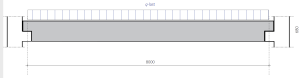
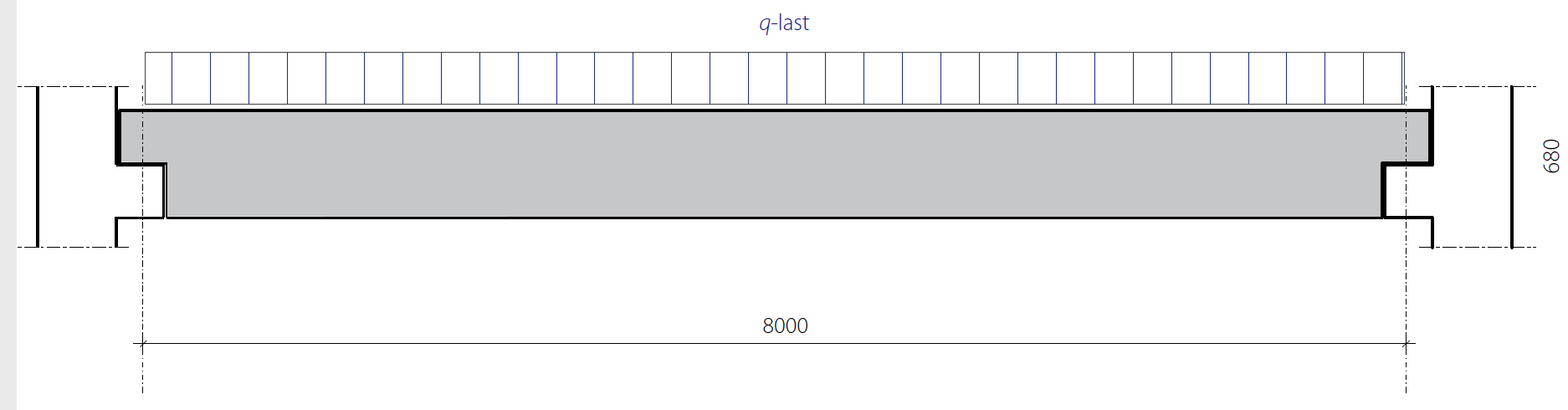
Reacties